A cold-wire feeder can create welding faults when it is connected to the wrong process, matched with the wrong consumables, or adjusted without controlling stickout, polarity, and wire-feed speed. You will be able to separate feeder, wire-delivery, shielding, and power-source faults, then specify a compatible system for automated production.
Key takeaways
- Confirm whether the electrode is powered or fed cold before troubleshooting.
- Inspect the spool, liner, drive rollers, and contact tip in feed order.
- Separate wire-delivery faults from arc, grounding, and shielding faults.
- Record each welding change so you can identify the cause, not chase symptoms.
First identify which wire-feeding process you are running
Determine whether welding current travels through the wire. In conventional flux-cored arc welding, the flux-cored electrode is powered: current passes from the power source through the contact tip and into the continuously fed wire, which creates the arc and deposits metal.
In a cold-wire system, the filler remains electrically unenergized and enters an independently generated arc or molten pool.
| Powered FCAW electrode | Unpowered cold filler |
|---|---|
| Wire creates the arc and carries welding current | Separate arc or heat source melts the filler |
| Uses an FCAW power source, contact tip, liner, drive rolls, and torch circuit | Uses a separate arc system plus a cold-wire feeder, guide, conduit, and control signal |
| Wire-feed speed directly affects amperage and deposition | Feed speed affects filler addition; arc current comes from another source |
| A missing or poorly sized contact tip disrupts current transfer | The guide and entry position control where filler reaches the pool |
| Typical FCAW-G or FCAW-S process | Robotic filler addition to TIG, plasma, laser, or another independent arc |
A cold-wire feeder is not a drop-in replacement for the powered feeder on an FCAW machine. Connect it without a separate heat source and the wire can stub, melt intermittently, produce poor penetration, or remain partly unmelted.
Check the wiring diagram, torch type, contact-tip arrangement, and controller settings before changing parameters. In robotic work, confirm that the cold wire’s angle and entry point are intentionally set; moving it away from the hottest part of the pool can change bead width or cause lack of fusion even when arc settings stay constant.
Trace feeding faults from the spool to the contact tip
Start at the spool, not the arc: a feeder motor can run while spool drag, roll slip, liner friction, or contact-tip drag reduces actual wire delivery. Confirm the setup first; powered FCAW electrode wire and electrically unpowered cold filler require different feeder, tip, control, and heat-source arrangements.
| Symptom | Likely cause | First mechanical check |
|---|---|---|
| Failure to feed | Locked spool, excessive brake drag, blocked liner, seized tip | Release the brake slightly, then hand-feed through the liner and tip |
| Intermittent feeding or wire slipping | Worn or contaminated grooves, wrong roll type, insufficient grip, crushed wire | Clean the rolls, match their groove to the wire diameter, and inspect for wear |
| Bird-nesting | Excessive roll pressure, kinked liner, sharp torch bend, blocked tip, excessive spool drag | Stop increasing pressure; inspect the liner, guide alignment, tip, and roll pressure |
| Burnback | Short stickout, hot or worn tip, delayed wire start, incorrect burnback setting | Fit the specified tip, check stickout, and verify the stop sequence |
Follow the wire path in order during cold wire feeder maintenance:
- Check spool rotation and brake drag; excessive resistance stores tension and pulls the wire from the rolls.
- Remove flux dust, packed debris, and flattened wire from the rolls and inlet guide.
- Replace a liner with kinks, blockage, or excessive friction, then route the torch without tight bends.
- Check tip bore and size against the wire; a partly fused tip causes drag, stubbing, and burnback.
A short manual-feed test does not clear cold wire feeder welding problems. Measure actual feed rate during robotic acceleration, with production torch routing and stickout.
Separate wire-delivery faults from arc and shielding faults
Follow the wire before blaming the feeder: a delivery fault changes wire arrival, while an arc or shielding fault changes heat, current, gas, or pool behaviour. Searches for “flux core welder cold wire feeder welding for problems” usually hide this split.
For flux core welder troubleshooting, record wire-feed speed, voltage, polarity, travel speed, stickout, and gas flow together. In powered FCAW, wire-feed speed largely sets current and deposition rate; changing it without correcting voltage or arc length causes stubbing, spatter, an unstable arc, or lack of fusion.
In a true cold-wire system, the filler carries no welding current, so check the independent arc and the wire-entry point.
- Porosity: check gas flow, leaks, nozzle blockage, draughts, and damp flux-cored wire before inspecting drive rolls. Moisture can also produce spatter, unstable arc behaviour, and hydrogen cracking in susceptible steels.
- Spatter or arc instability: verify electrode classification and polarity. Gas-shielded FCAW commonly uses DCEP; many self-shielded wires use DCEN. Follow the wire manufacturer’s data sheet, not the power source’s default.
- Undercut: check excessive voltage, long stickout, high current, or travel speed before adjusting feeding hardware.
- Lack of fusion: check low heat input, fast travel, poor work return, and a cold-wire entry point outside the hottest part of the pool.
- Inconsistent bead size: compare actual wire delivery with programmed speed, then check travel motion and robotic wire angle, distance, and entry position.
Change one recorded welding variable at a time
Record a stable baseline before changing anything: wire classification, polarity, contact-tip size, stickout, voltage, wire-feed speed, inductance, travel speed, gas flow, and robotic wire-entry position. Change one recorded variable, run the same test length, and compare bead shape, penetration, spatter, and actual delivery.
- Confirm the wire classification and diameter against the manufacturer’s procedure data. Do not substitute a similar-looking FCAW or cold-filler wire.
- Verify polarity at the power source and torch. Self-shielded and gas-shielded flux-cored wires can require different polarity; follow the electrode data sheet.
- Install the specified contact-tip size. A loose tip causes erratic current transfer; an undersized or worn tip creates drag and burnback.
- Measure stickout from the contact tip to the work and hold it within the procedure range. A long stickout lowers arc current; a short one increases tip heating.
- Change voltage separately from wire-feed speed. Wire-feed speed largely sets current and deposition rate, so changing it can cause stubbing, spatter, or lack of fusion.
- Adjust inductance only after voltage and wire-feed speed are stable; record the setting and observe arc smoothness and bead wetting.
- Hold travel speed constant during each trial. Faster travel narrows the bead and can reduce fusion.
- Confirm gas type, flow at the torch, leaks, and nozzle condition; use no shielding gas when the wire data sheet specifies self-shielded operation.
- In robotic welding, record wire angle, entry distance, and entry point, then change one position at a time.
- Include cold wire feeder maintenance: remove flux dust, inspect the liner and rolls, check spool drag, and verify actual feed rate under production acceleration.
Specify a compatible system before you buy or automate
Do not approve a “flux-core compatible” label until the supplier identifies the process. A powered FCAW system uses the wire as the electrode and sends welding current through its contact tip; a cold-wire feeder adds unenergized filler to a separate arc and molten pool.
Treating one as a drop-in replacement for the other can cause wire stubbing, poor penetration, and incomplete melting.
1. State the process in the purchase specification: FCAW-G or FCAW-S for powered welding, or cold filler with the independent arc source, wire guide, torch, and control signal identified.
2. Confirm the power-source input voltage and frequency, output range, polarity settings, rated duty cycle, and the feeder’s control interface. Match polarity to the electrode manufacturer’s data sheet, not to an assumption about flux-cored wire.
3. Check the complete wire path: spool capacity, liner length and material, knurled drive rolls sized for cored wire, conduit, torch, and contact-tip diameter. Excessive roll pressure can crush tubular wire and release flux.
4. For robotic work, record the wire-entry position, travel-speed relationship, feeder command, and independent heat-source settings. Run a dry-feed test before striking an arc.
5. While sourcing flux core welding equipment in Pune, confirm local stock of matching tips, liners, drive rolls, and FCAW-G or FCAW-S wire. Ask ATE WELDING ENGINEERING ROBOTICS AND AUTOMATION PRIVATE LIMITED to document these interfaces rather than accepting a generic package description.
Keep opened wire sealed and dry; humidity can turn a sound specification into porosity and unstable feeding.
Related product
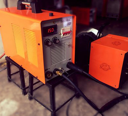 | The Cold Wire Feeder Welding Cold Wire Feeder Welding – Precision and Efficiency in Welding At ATE Welding Engineering & Robotic Automation, we offer Cold Wire Feeder Welding... View product → |
Frequently asked questions
How do you identify which wire-feeding process you are running?
Check whether welding current travels through the wire. In conventional flux-cored arc welding, the powered electrode carries current from the power source through the contact tip. A cold wire feeder delivers unpowered filler wire into a separate welding arc or molten pool.
Where should you start when troubleshooting cold wire feeder welding problems?
Trace the wire path in order: spool, spool brake, inlet guide, drive rollers, liner or guide tube, outlet guide, and contact tip or deposition point. Inspect each part for drag, misalignment, contamination, wear, or incorrect size.
How do you separate wire-delivery faults from arc and shielding faults?
First check whether the wire advances smoothly at the commanded speed. If feeding is erratic, inspect the mechanical delivery path. If feeding is stable but the arc is unstable, check polarity, grounding, contact-tip condition, voltage, current, gas flow, and shielding coverage.
What should you record when changing flux core welding settings?
Record wire diameter and type, wire-feed speed, voltage, current, polarity, travel speed, gas flow, contact-tip size, and the observed defect. Change one variable at a time so the result identifies a cause.