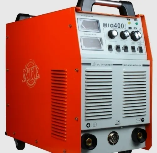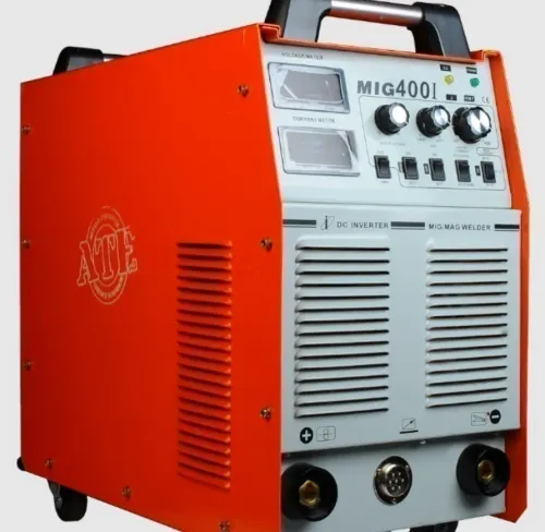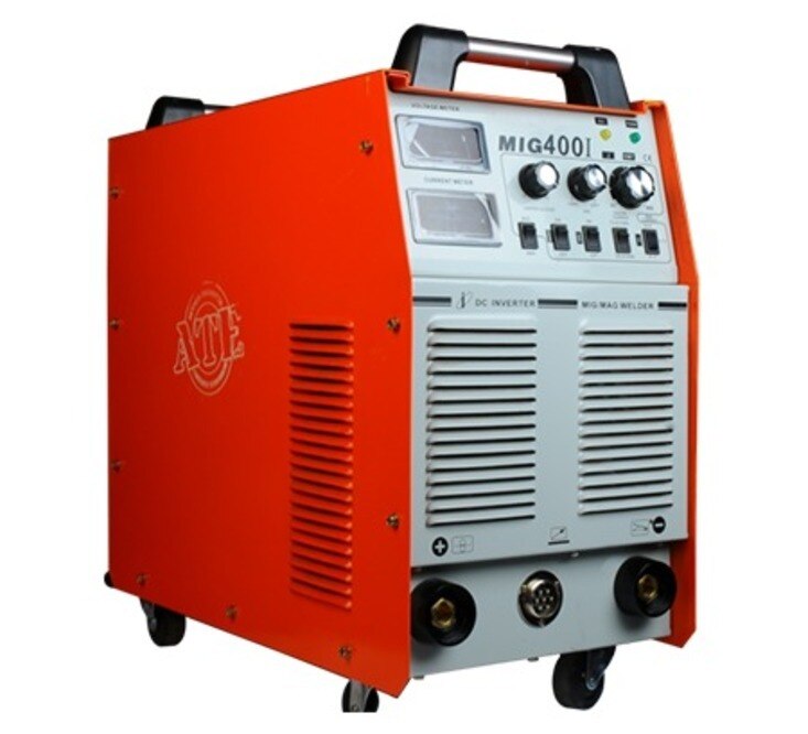
A machine labelled MIG/TIG can mean a true dual-process power source, a MIG unit with lift-TIG capability, or two welding systems sharing one package. By checking process controls, output at your working duty cycle, wire and gas compatibility, TIG functions, input power, and production interfaces, you can reject machines that look versatile on paper but cannot perform your actual work.
Key takeaways
- Confirm whether the machine offers AC TIG or DC TIG only.
- Match amperage, duty cycle, and input power to your material and workload.
- Check wire-feed control, polarity options, gas connections, and torch capacity.
- Verify sequencing, robot interfaces, service support, and replacement-part availability.
Identify What the MIG/TIG Label Actually Includes
A MIG/TIG label can describe a true dual-process machine, a MIG welding machine with limited lift-TIG capability, or two separate systems in one enclosure. The label alone does not prove AC TIG: many combination machines provide DC TIG only and cannot weld aluminium by AC TIG.
Before buying, verify these MIG TIG welder features:
- Selectable MIG, TIG, and flux-cored modes, plus output amperage range, open-circuit voltage, voltage adjustment, wire-feed speed range, and TIG current control.
- AC output, adjustable AC balance, AC frequency, and high-frequency starting if you need aluminium TIG. Without these specifications, treat the TIG function as DC TIG.
- TIG arc-start behaviour. High-frequency start avoids tungsten contact; lift-arc start requires controlled contact and lift and does not establish foot-pedal or sequencing capability.
- Inductance or arc-control adjustment with repeatable settings and useful parameter guidance. Inductance changes current-rise behaviour and short-circuit characteristics; it cannot correct wrong voltage, wire-feed speed, contact-tip-to-work distance, or shielding gas.
- For pulse MIG, request a sample weld or qualified procedure using your actual wire, gas, thickness, and travel speed. Single-pulse and double-pulse are not equivalent checkbox features because transfer, heat input, arc-length control, and appearance can differ.
A machine with impressive mig welder features can still fail your job if its modes or controls do not match the process. Confirm the actual configuration before comparing prices.
Match Output, Duty Cycle, and Input Power to the Job
A MIG welding machine must match the material thickness, weld length, production cycle, and available power—not just the headline amperage. Confirm the output at your intended amperage and input voltage, then check whether the machine can sustain that output without repeated thermal shutdowns.
Duty cycle normally uses a 10-minute period. Compare ratings at the same operating point:
| Rating | Arc time in 10 minutes | What the comparison shows |
|---|---|---|
| 60% at 200 A | 6 minutes | Not equivalent to 300 A operation |
| 20% at 300 A | 2 minutes | Higher output, but much shorter continuous weld time |
| Your job’s rating | Calculate from actual cycle | Include arc time, pauses, repositioning, and cooling |
Ask for the test temperature and standards basis. A 40 °C ambient reference under IEC/EN practice is common; a percentage without this information is incomplete.
Check these mig tig welder features against the facility installation:
- Single-phase or three-phase supply, nominal voltage range, voltage tolerance, maximum input current, breaker size, plug arrangement, grounding, and conductor size.
- Rated output at the site’s actual voltage; dual-voltage labeling does not guarantee equal duty-cycle performance on both supplies.
- Generator capacity and waveform compatibility. Inverter welders can react poorly to unstable or unsuitable generator output.
- Extension-lead length and conductor size. Voltage drop can reduce arc and wire-feed performance.
Follow the manufacturer’s overcurrent, grounding, conductor, and generator instructions, plus applicable electrical codes.
Check Wire Feeding, Polarity, and Shielding-Gas Hardware
A feeder on a MIG welding machine is suitable only if it supports your actual wire, alloy, spool, and gun arrangement. A stated range such as 0.6–1.6 mm does not replace a wire-specific feeder kit, especially for soft aluminium.
1. Verify solid-wire diameters, self-shielded and gas-shielded flux-cored diameters, spool size, drive-roll groove geometry, liner type, contact-tip sizes, motor torque, and supported wire alloys. Confirm that the feeder kit matches each wire.
2. Check polarity selection and the manufacturer’s procedure for every electrode. A flux core welder set to the wrong polarity can produce unstable arc behaviour, excessive spatter, and poor weld performance.
3. Compare the feed path before choosing among these mig welder features:
| Conventional gun and liner | Longer path through the liner | Suitable for supported steel wire; soft aluminium is more prone to bird-nesting |
|---|---|---|
| Spool gun | Short wire path at the gun | Improves aluminium feeding when the machine supports its control connection |
| Push-pull gun | Motorised gun plus feeder drive | Stabilises soft wire over a longer reach; verify compatible controls |
4. Inspect gas type, regulator and flowmeter connection, hose fittings, solenoid operation, gas-flow range, and shutoff behaviour. Gas-shielded MIG and FCAW need protection from wind; self-shielded FCAW avoids cylinder gas but creates more smoke, spatter, and slag, requiring slag removal and post-weld cleaning.
Match polarity, wire diameter, and operating procedure to the electrode before welding outdoors.
Verify TIG Starting, Sequencing, and Torch Capacity
A TIG label proves little: a MIG/TIG welder may offer full TIG control, lift-TIG only, or DC TIG without aluminium capability. Look for AC output, adjustable AC balance, AC frequency, and high-frequency starting if you need to weld aluminium.
| Option | What it does | When it applies | Limitation |
|---|---|---|---|
| High-frequency start | Starts the arc without tungsten-to-work contact | Contamination-sensitive work and clean production starts | Adds high-frequency interference and cost |
| Lift-arc start | Uses controlled contact, then lifts the tungsten | Lower-cost equipment or interference-sensitive sites | Requires consistent technique and can contaminate tungsten |
| Air-cooled torch | Rejects heat through the torch body and ambient air | Intermittent, low-to-moderate current welding | Overheats sooner at high duty cycle |
| Water-cooled torch | Circulates coolant through the torch | Sustained high-current TIG | Requires a compatible cooler, hoses, and torch |
Confirm the actual torch connection, remote amperage interface, and foot-pedal support. A remote socket alone does not prove that a pedal or full sequence controller works.
- Ask whether the controls include pre-flow, start current, upslope, peak current, background current, downslope, crater or end current, post-flow, and pulse frequency.
- Distinguish a two-step torch switch from a full sequence controller. The switch may only start and stop current, leaving thin material vulnerable to excessive heat and crater cracking.
- Compare each torch rating at its stated duty cycle and AC or DC condition. For the useful mig tig welder features, verify the complete sequence rather than trusting a TIG label or a mig tig welder mode icon.
Evaluate Production Controls, Robot Compatibility, and Support
A MIG/TIG welder is production-ready only when its controls remain repeatable and serviceable after installation, not merely impressive during a demonstration. For a manual MIG welding machine, check whether the MIG welder features include stored jobs, password lockout, remote adjustment, weld-parameter logging, error history, and exportable records.
| Control | Manual production | Robotic or mechanized production |
|---|---|---|
| Settings | Repeatable voltage and wire-feed speed; stored programs | Deterministic start/stop; wire-feed speed or program selection |
| Feedback | Displayed parameters and error history | Arc-valid feedback and fault status |
| Safety | Remote stop and locked settings | Emergency-stop integration with the robot controller |
| Interfaces | Remote adjustment and data export | Verified analog I/O, fieldbus, or proprietary protocol |
Do not treat analog I/O, fieldbus, and proprietary robot protocols as interchangeable. Confirm compatibility with the exact robot controller, then verify gas control, burnback, crater fill, wire retract, touch-sensing, seam tracking, and collision or crash-box integration.
These functions need coordinated timing among the power source, feeder, torch, and robot; missing timing signals create wire sticking, poor restarts, or collision damage.
Ask for a written configuration containing:
- Interface map and I/O list
- Wire-and-gas procedure
- Sample weld using your material and wire
- Duty-cycle basis and test conditions
- Commissioning, training, and maintenance scope
ATE WELDING ENGINEERING ROBOTICS AND AUTOMATION PRIVATE LIMITED can serve as a technical comparison point if it supplies those documents rather than a mode count. Choose verified compatibility, accessible records, spare-parts support, and defined commissioning responsibility over a crowded front panel.
Related product
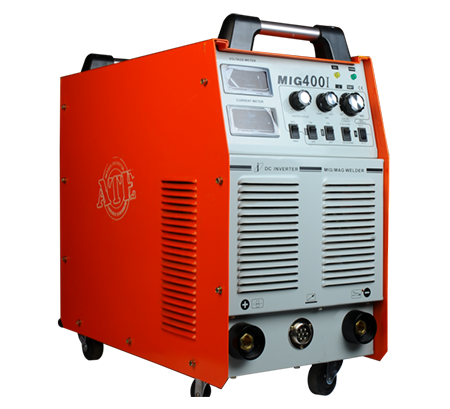 | MIG Welding Machine High-Speed and Versatile Welding Solutions At ATE Welding Engineering & Robotic Automation, we offer advanced MIG (Metal Inert Gas) welding machines... View product → |
Frequently asked questions
Does every MIG/TIG welder provide AC TIG?
No. Many combination machines provide DC TIG only, so they cannot weld aluminium by AC TIG. Confirm the TIG output type before buying.
How do you match a MIG/TIG welder to a job?
Compare required amperage, duty cycle, input voltage, material thickness, and available power with the machine’s specifications.
Which wire-feeding and shielding-gas features matter?
Check wire diameter range, feed-speed control, polarity selection, spool or feeder capacity, gas connections, regulator compatibility, and support for solid wire or flux-cored wire.
What TIG features should you verify?
Check lift or high-frequency starting, pre-flow and post-flow, current sequencing, torch rating, remote control compatibility, and whether the machine supports AC or DC TIG.
What should manufacturers check for robotic welding compatibility?
Verify communication interfaces, remote parameter control, duty cycle at production current, torch and feeder integration, documentation, commissioning support, and access to replacement parts.