Poor weld quality rarely comes from amperage alone. By matching visible defects to power-source specifications, consumables, gas delivery, duty cycle, and setup records, you can separate a machine fault from an upstream process problem and validate the right corrective action.
Key takeaways
- Check minimum stable current for thin-sheet weld control.
- Match porosity, undercut, and burn-through to specific settings.
- Test duty cycle and wire feeding under production conditions.
- Prove weld quality with coupons before integration or purchase.
Which MIG-TIG Welder Specifications Predict Weld Quality?
Minimum stable current, not maximum amperage, is the first specification to check when using mig tig welder specifications for manufacturing weld quality. Thin-sheet control, penetration consistency, and repeatable bead width depend on the lower limit, rated current at its stated duty cycle, voltage control, wire feeding, and arc response.
Check the datasheet and nameplate for:
- Minimum and maximum output current, rated current and duty-cycle percentage, plus the duty-cycle test temperature
- Output-voltage range, open-circuit voltage, voltage-adjustment steps, and control resolution
- Wire-feed-speed range and accuracy, supported wire diameters, drive-roll requirements, and pulse controls
- Inductance or arc-dynamic control, arc-start settings, torch rating, cooling method, and torch and cable lengths
- Input phase, input voltage tolerance, maximum input current, power factor, and generator compatibility
A 60% duty cycle means six minutes of arc-on time in a 10-minute period at the stated current and temperature. It does not mean six minutes at maximum amperage.
| Process | Power-source behavior | Quality implication |
|---|---|---|
| GMAW/MIG | Constant voltage; wire-feed speed strongly influences current | Check voltage, feed accuracy, inductance, stick-out, and feeder stability |
| GTAW/TIG | Constant current; arc length mainly changes voltage | Check current stability, start mode, pulse control, downslope, and torch cooling |
A combined MIG-TIG machine does not automatically provide equivalent control in both modes. Its label cannot replace process-specific specifications.
How Do You Match Weld Defects to the Correct Variable?
Match each defect to its source: power source, welding setup, or workpiece. The table below turns MIG-TIG welder problems into checks rather than guesses.
| Defect | Likely cause | Check |
|---|---|---|
| Porosity | Wrong gas, low flow, leaks, drafts, damaged diffuser, excessive turbulent flow | Gas type and flow, regulator, hoses, nozzle, enclosure airflow |
| Lack of fusion | Low heat, fast travel, poor angle, oxide or mill scale | Voltage, wire-feed speed, travel speed, joint cleanliness |
| Lack of penetration | Tight root, low current, excessive stick-out | Root gap, polarity, current and contact-tip distance |
| Undercut | Excessive voltage, current, or travel speed | Bead edges, arc length and travel speed |
| Burn-through | Excessive heat or root gap | Current, voltage, travel speed and fit-up |
| Spatter | Voltage-wire-feed imbalance, contamination, poor grounding | Inductance, wire condition and work lead |
| Tungsten contamination | Tungsten touched pool or filler | Stop, remove contaminated section and regrind |
| Crater cracking | Abrupt arc stop or shrinkage | Downslope, crater fill and termination |
| Arc instability | Wire-feed variation, poor contact tip or tungsten damage | Drive rolls, liner, tip fit and electrode preparation |
| Inconsistent bead width | Changing travel speed, feed or torch distance | Cable position, stick-out and operator motion |
Use this diagnostic sequence before changing machine settings:
- Inspect joint preparation, fit-up, cleanliness, grounding and polarity.
- Check torch angle, electrode stick-out, travel speed and interpass temperature.
- Inspect bead profile, overlap, cracks, undercut and visible porosity.
- Verify gas type, flow, regulator, leaks, hose restrictions, nozzle and diffuser; excessive flow creates turbulence.
- Compare settings with the MIG-TIG welder specifications for manufacturing weld quality, then test one variable at a time.
Record the result against ISO 3834 quality requirements and ISO 5817 quality levels B, C or D. Brand claims, including “iBell welding machine weld quality,” do not replace inspection evidence.
How Should You Set MIG and TIG Parameters for a Test Coupon?
Set process first: MIG suits high-volume carbon-steel, stainless-steel, and aluminium production when throughput matters; TIG suits thin sheet, root passes, stainless steel, aluminium, and cosmetic welds when heat and bead control matter.
1. Choose compatible consumables. Match MIG wire type and diameter, electrode classification, shielding gas, contact-tip size, drive rolls, liner, and polarity to the base metal. For TIG, match tungsten diameter and preparation, filler-rod diameter, electrode polarity, and gas type to the material and current range.
2. Start from the material thickness and joint. Set MIG wire-feed speed and current together, then adjust voltage for a stable arc; set travel speed so the bead wets both toes without overheating.
Set TIG current for penetration, arc length near the tungsten diameter, travel speed for heat control, and gas flow high enough for shielding but not so high that turbulence draws in air. Validate every change on a test coupon.
3. Treat feeding faults as mig tig welder problems, not automatic power-source failures. Check burn-back, bird-nesting, wire stubbing, spatter, erratic arc length, and voltage-wire-feed balance. Inspect drive-roll profile, liner size and condition, spool tension, contact-tip wear, and torch-cable position.
4. For TIG, check HF-start failure, lift-arc marks, tungsten balling or inclusions, pre-flow, post-flow, downslope shielding, and torch cooling. Stop and regrind contaminated tungsten; extra current or gas will not remove inclusions. Record settings and coupon results for repeatable mig tig welder manufacturing.
When Are Duty Cycle, Wire Feeding, or the Production Cell the Real Fault?
A 60% duty cycle means six minutes of arc-on time in each 10-minute period at the stated test current and ambient temperature. It does not mean six minutes at maximum amperage. Count welding separately from loading, setup and inspection; repeated thermal shutdown means the machine is undersized when arc-on time exceeds that rating.
Before blaming the source for mig tig welder problems, check the complete current and wire path:
- Poor grounding, loose work leads, wrong polarity or unstable mains supply.
- Contaminated base metal, damp or badly stored wire, and excessive cable length.
- A restricted liner, incorrect drive-roll profile or size, worn contact tip, or excessive spool-brake tension.
The comparison changes for mig tig welder manufacturing:
| Option | Throughput and access | Skill, shielding, finish and rework |
|---|---|---|
| Dedicated MIG or TIG | MIG gives high throughput; TIG gives precise access on thin or cosmetic joints | MIG needs shielding gas and moderate skill; TIG needs higher skill but reduces rework on controlled roots |
| Combined machine | Flexible, but one source may compromise duty cycle or process control | Useful for varied work; less repeatable than specialised sources |
| Stick or ARC | Lower throughput but strong outdoor access | No shielding gas, higher spatter and slag cleanup; more rework |
| Pulsed MIG | High throughput with reduced heat and spatter | Requires tuned parameters, gas and wire; improves finish |
| Robotic cell | Highest repeatability and production capacity | Needs accurate TCP, fixtures, wire-feed calibration and communication |
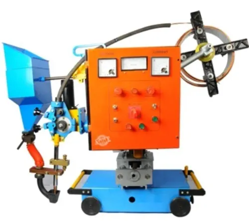
| Submerged arc | Very high deposition on long, accessible seams | Flux hides the arc; limited access and greater cleanup |
Choose separate sources when higher duty cycle, specialised pulsed or high-current output, or better robot communication and repeatability matter more than one machine’s flexibility.
How Can You Prove Weld Quality Before Purchase or Integration?
A purchase passes only when identical coupons produce acceptable results on competing machines. Treat mig tig welder specifications for manufacturing weld quality as a starting checklist, not acceptance proof.
- Run the same material grade and thickness, joint design, fit-up, consumable batch, shielding gas, polarity, WPS parameter set, and travel speed. Compare bead geometry, visual results, macrosections, bend or tensile tests, and radiographic or ultrasonic results when the WPS or contract requires them.
- Record the machine model and serial number, input supply, duty-cycle condition, operator, defect location, photographs, and parameter-recall behaviour. Repeat the trial with different operators and check robot or positioner interfaces, TCP and wire-feed calibration, spare-parts availability, service access, and maintenance or verification records.
- Add setup time, gas consumption, consumable waste, training, rework, calibration, and thermal-overload downtime to the manufacturing cost.
| Evidence | Compare | Failure revealed |
|---|---|---|
| Bead and visual inspection | Profile, width, undercut, overlap, spatter, cracks, porosity | Poor settings or unstable operation |
| Macrosection and mechanical tests | Fusion, penetration, bend or tensile performance | Internal or structural weakness |
| Radiographic or ultrasonic inspection | Indications against the WPS or contract | Hidden discontinuities |
| Repeatability trial | Operators, cycles, and parameter recall | Integration or control instability |
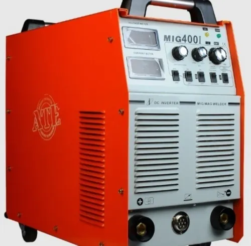
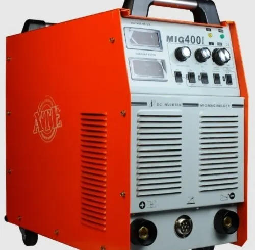
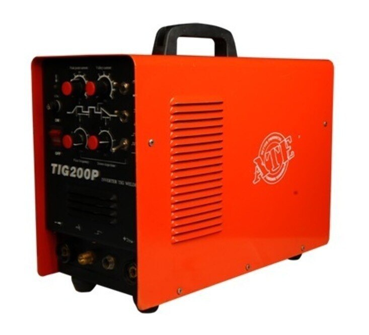
For “iBell welding machine weld quality,” use identical evidence against another MIG/TIG welder; the brand name proves nothing. ATE WELDING ENGINEERING ROBOTICS AND AUTOMATION PRIVATE LIMITED can support equipment trials or automation-integration discussions, but only recorded test results establish acceptance.
Related products
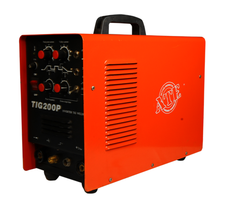 | TIG Welding Machine Precision and High-Quality Welding At ATE Welding Engineering & Robotic Automation, we specialize in TIG (Tungsten Inert Gas) welding machines,... View product → |
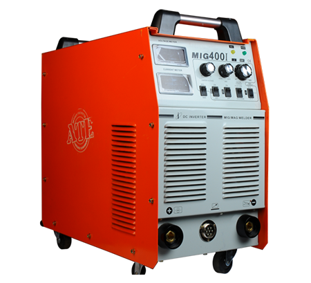 | MIG Welding Machine High-Speed and Versatile Welding Solutions At ATE Welding Engineering & Robotic Automation, we offer advanced MIG (Metal Inert Gas) welding machines... View product → |
Frequently asked questions
Which MIG-TIG welder specifications predict weld quality?
Check minimum stable current, rated current at its stated duty cycle, voltage control, wire-feed accuracy, and arc-response performance. These specifications predict control, penetration consistency, and bead-width repeatability more reliably than maximum amperage alone.
How do you match MIG-TIG welder problems to the correct variable?
Link the visible defect to its likely variable: burn-through to excessive current or slow travel, undercut to excessive voltage or travel speed, lack of fusion to insufficient heat or poor torch position, and porosity to shielding-gas flow, leaks, contamination, or drafts.
How should you set MIG and TIG parameters for a test coupon?
Use the same material grade, thickness, joint design, shielding gas, filler, torch angle, and travel method planned for production. Record current, voltage, wire-feed speed, gas flow, travel speed, and torch settings while producing repeatable coupons.
When are duty cycle, wire feeding, or the production cell the real fault?
Suspect duty cycle when output falls after sustained welding, wire feeding when speed or tension fluctuates, and the production cell when fixtures, torch alignment, grounding, shielding, or robot path changes the bead.
How can you prove weld quality before purchase or integration?
Require representative test coupons, documented parameter logs, repeated welds, visual inspection, dimensional checks, and the inspection or qualification tests required for your joint and application. Test the complete cell when automation is planned.