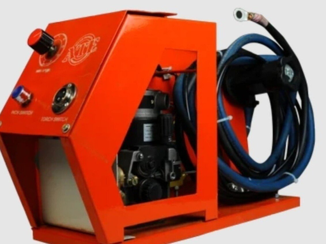
A flux-cored wire feeder can stop delivering wire because of resistance at the spool, drive rolls, liner, contact tip, or torch cable long before its motor fails. By tracing the wire path in order, checking the FCAW settings and consumable condition, and separating transport faults from body-part contamination, you can identify the cause instead of repeatedly replacing feeder parts.
Key takeaways
- Inspect the tip, liner, cable bend, roll pressure, and spool before replacing the feeder.
- Measure resistance through the complete wire path, not only at the drive rolls.
- Match drive rolls, liner, contact tip, and spool settings to the wire diameter.
- Separate wire transport faults from voltage, polarity, gas, and welding-parameter problems.
Which failure mode is stopping wire delivery?
A bird-nest at the feeder inlet usually means resistance or lost restraint downstream, not a failed motor. Check for a plugged or undersized contact tip, an unseated liner, a sharp gun-cable bend, excessive roll pressure, or spool overrun before replacing the feeder.
| Symptom | Likely mechanical cause | What to confirm |
|---|---|---|
| Bird-nesting | Downstream restriction, loose liner seating, sharp bend, excess roll pressure, or spool overrun | Wire movement and contact-tip passage |
| Wire slip at rolls | Wrong groove, low pressure, spool drag, or misalignment | Roll rotation versus wire motion |
| Burnback into contact tip | Wire stops before the arc extinguishes; tip bore is restricted or stick-out is too short | Delivered wire length and tip condition |
| Erratic arc starts or stubbing | Intermittent delivery, tip blockage, poor restraint, or parameter error | Actual wire exit during jog |
| Drive-roll seizure | Contamination, excessive pressure, damaged wire, or bearing failure | Roll rotation with wire removed |
| Liner blockage | Kink, debris, compressed sheath, or tight cable routing | Free passage with cable straightened |
| Contact-tip blockage | Spatter, incorrect bore, oval wear, or fused wire | Tip removed and inspected |
| Intermittent delivery | Spool overrun, encoder error, liner friction, or roll slip | Commanded length versus delivered length |
For flux core welder wire for feeding problems, cut the wire at the feeder, straighten or disconnect the gun, and jog a measured length. If delivery becomes correct, the restriction is downstream; if rolls slip without gun load, investigate spool drag, pressure, geometry, motor torque, or calibration.
Zinc coating, stamping oil, sealers, mill scale, and changing gaps cause arc defects without proving automotive welding wire issues.
How do you isolate resistance along the wire path?
A measured jog with the gun cable straightened or disconnected separates downstream resistance from feeder-side faults. Cut the wire at the feeder, command a fixed length, and watch both drive-roll slip and the wire leaving the outlet.
1. Check spool rotation and brake drag first. The spool must unwind without surging or needing excessive pull. Inspect loose wraps, crossed wire, the inlet guide, and damaged spool flanges or crushed wire.
2. Verify drive-roll alignment, groove selection, pressure, and motor response. Confirm that the groove matches the wire diameter and construction, then set pressure only high enough to prevent slip.
If the rolls slip with no gun load, investigate spool drag, roll pressure or geometry, motor torque, and feeder calibration rather than assuming a flux core welder wire feed problem.
3. Examine the liner for correct length, material, contamination, and internal diameter. Check that both ends are clean and that the liner is firmly seated against the diffuser. Inspect tight bends in the gun cable, because a sharp bend can create a welding wire feeding failure and a bird-nest at the feeder.
4. With the gun connected, repeat the same measured jog. Delivery with the gun removed but failure when connected identifies a downstream restriction. Check the contact tip for spatter, an undersized or damaged bore, and poor alignment; do not treat every contact-tip restriction as a feeder motor fault.
Compare the commanded length with encoder feedback. An encoder error can report correct speed while the wire slips, so confirm actual wire travel with a marked section of wire before replacing the feeder.
Which drive-roll, spool, liner, and tip settings prevent repeat failures?
Choose the roll by wire construction and diameter, not by pressure alone: knurled rolls commonly grip tubular flux-cored wire, while smooth V-grooves suit many solid steel wires.
A groove that fits the diameter but not the construction can slip or crush the sheath, creating cold wire feeder welding problems and an intermittent welding wire feeding failure.
| Option | Correct choice | Failure from confusion |
|---|---|---|
| Tubular flux-cored wire | Knurled groove matching the actual diameter | Sheath crushing or roll slip |
| Solid steel wire | Smooth V-groove matching the actual diameter | Poor grip or surface damage |
| Any wire | Roll, feeder, and wire construction rated together | Unstable delivery despite correct nominal size |
Set pressure only high enough to stop slip. Perform a controlled stall test: briefly restrain the wire downstream and confirm that the rolls slip before the wire deforms; excessive pressure crushes the sheath, sheds contamination, and creates intermittent delivery.
Check these settings before changing the feeder motor:
- Confirm actual wire diameter, wire type, spool size, feeder capacity, loose wraps, and brake setting. Test spool inertia at the robot’s real acceleration; a tight brake or sudden spool pull can mimic drive failure.
- Use a liner with the correct internal diameter and material. Keep its ends clean and seated, use the shortest practical length, and remove tight gun-cable bends.
- Match the contact tip to the actual wire diameter, align it with the diffuser, and replace it when the bore is oval, enlarged, spattered, or worn.
- Record stick-out and contact-tip-to-work distance with the same setup. A worn tip or changing distance can turn sound delivery into erratic starts and burnback.
When is the problem wire transport, and when is it welding setup?
If the delivered wire length is steady, the fault is welding setup, not transport; if it changes, slips, stops, or binds under the same command, investigate the wire path. Poor penetration, spatter, stubbing, and unstable starts can arise from either a flux core welder wire feed problem or automotive welding wire issues.
- Compare the job with the manufacturer’s welding procedure specification, wire data sheet, and classification information: AWS A5.20 covers carbon-steel flux-cored wire, while AWS A5.29 covers low-alloy steel flux-cored wire. Confirm wire-feed speed, voltage, arc length, inductance, shielding arrangement, polarity, diameter, joint design, and machine limits. Do not infer polarity from “flux-cored”: many gas-shielded wires use DCEP, while many self-shielded wires use DCEN. Wrong polarity can mimic a feeder fault.
- Check actual wire motion, drive-roll slip, and delivered length while jogging the feeder. In a constant-voltage FCAW system, increasing wire-feed speed raises amperage; it can change arc length and penetration rather than simply improve delivery. If wire movement is consistent, correct stickout, contact-tip-to-work distance, torch angle, travel speed, and programmed parameters.
- Inspect rust, humidity, condensation, oil, drawing residue, damaged sheath material, and crushed spools. Contamination increases liner friction and destabilises the arc; moisture can contribute to hydrogen-related defects. Store opened wire under the wire manufacturer’s stated conditions, not as indefinitely shelf-stable solid MIG wire.
Clean zinc coating, stamping oil, sealers, mill scale, and changing joint gaps before blaming the feeder. A worn or blocked contact tip can also create burnback and arc instability even when transport is sound.
How should an automotive cell prevent recurring feeder failures?
Lock the production program before changing hardware. A controlled stick-out, torch angle, travel speed, wire-feed speed, and acceleration prevents a marginal setup from becoming a recurring welding wire feeding failure.
1. Record the approved stick-out and torch angle in the robot program. Set wire-feed speed and travel speed together, then test spool drag at the programmed acceleration. Excess brake drag causes roll slip; insufficient drag lets the spool overrun and form loops.
2. Set a contact-tip replacement interval by weld length or arc hours, not only by visible damage. Inspect the liner at each scheduled service for contamination, crushed ends, tight bends, and poor seating.
Record a short-length delivery test: cut the wire at the feeder, jog a measured length, and compare commanded with delivered length while watching roll slip.
3. Treat long conduits and remote push-pull systems as synchronization systems. Check encoder scaling, commanded speed, feeder calibration, and start-stop timing. A secondary feeder pushing too fast buckles wire; pushing too slowly makes the primary feeder pull and slip.
4. Separate powered FCAW from cold wire feeder welding problems in laser or TIG applications. Check guide-tube friction, straightener adjustment, wire alignment, nozzle position, and synchronization with travel speed—not contact-tip polarity.
For a cell review, ATE WELDING ENGINEERING ROBOTICS AND AUTOMATION PRIVATE LIMITED can verify feeder capacity, roll and liner compatibility, torch routing, and interface timing against the production program before replacement equipment is selected.
Related product
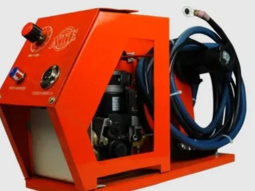
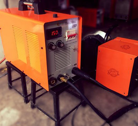 | The Cold Wire Feeder Welding Cold Wire Feeder Welding – Precision and Efficiency in Welding At ATE Welding Engineering & Robotic Automation, we offer Cold Wire Feeder Welding... View product → |
Frequently asked questions
Which failure mode is stopping wire delivery?
A bird-nest points to downstream resistance or lost restraint. Check the contact tip, liner seating, gun-cable bend, roll pressure, and spool overrun.
How do you isolate resistance along the wire path?
Inspect and test each section separately: spool, inlet guide, drive rolls, liner, contact tip, and gun cable. Remove restrictions before changing feeder components.
Which drive-roll, spool, liner, and tip settings prevent repeat failures?
Use the roll profile and diameter specified for the wire, set enough pressure to prevent slip without crushing the wire, seat the liner fully, and match the tip bore to the wire.
When is the problem wire transport, and when is it welding setup?
Transport faults cause bird-nests, slipping, irregular delivery, or motor overload. Welding setup faults cause poor arc performance after stable wire delivery, including incorrect polarity, voltage, inductance, or shielding.
How should an automotive cell prevent recurring feeder failures?
Record wire diameter, roll pressure, liner and tip changes, cable routing, feeder alarms, and failure location. Add inspection intervals and verify delivery during scheduled cell maintenance.