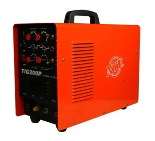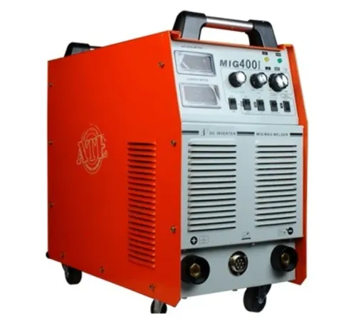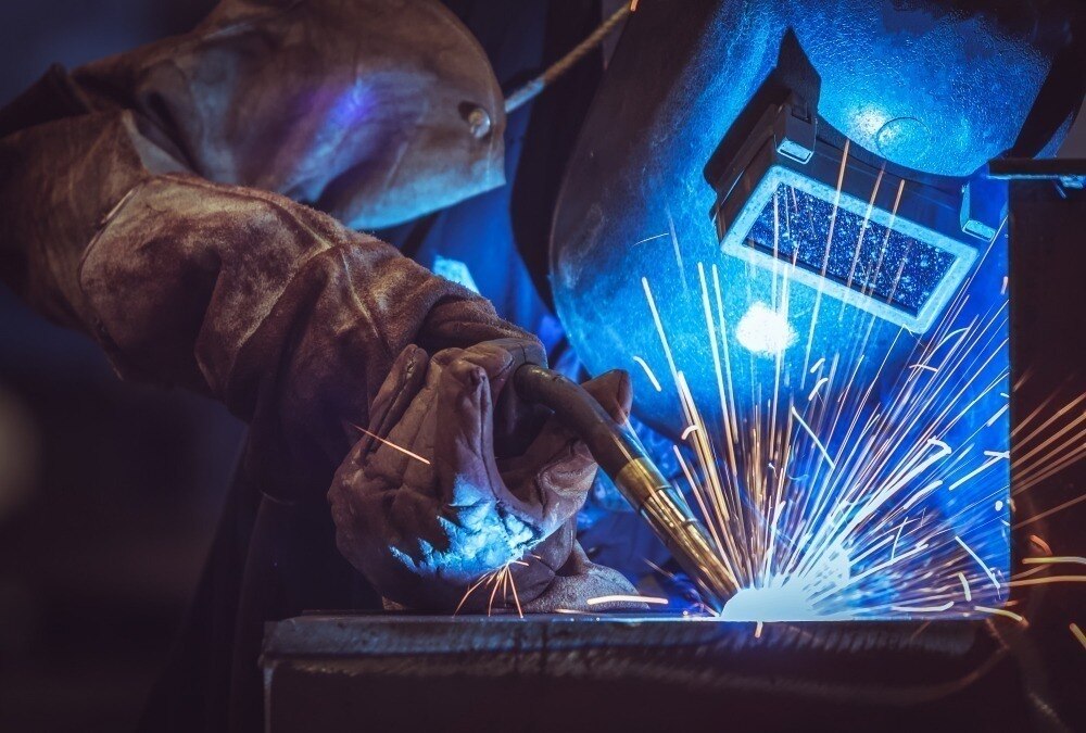
Choosing an electric welder machine for automotive production starts with the joint, material stack-up and access—not with the machine label. You will be able to distinguish resistance spot welding from arc processes, compare MIG, flux-cored, TIG, stick and submerged arc options, and request specifications that match your production method, duty cycle and quality controls.
Key takeaways
- Use resistance welding for high-volume sheet-metal body assembly.
- Choose MIG for flexible automotive fabrication and flux core for specific outdoor or contaminated work.
- Match wire, shielding gas, current range and duty cycle to the material and joint.
- Approve a robotic cell only after testing access, fixturing, cycle time and weld quality.
Which welding process fits each automotive production task?
An electric welder machine for automotive production is a complete system, not a power source alone. The power source creates current; the welding process controls how it enters the joint. The torch or gun, wire feeder, fixture, controller and robotic cell determine access, feeding, positioning and repeatability.
Together, they form the automotive welding machine you must evaluate.
| Process | Best-fit automotive task | Main limitation |
|---|---|---|
| Resistance spot welding | Body-in-white overlapping flanges | Electrode access and shunting |
| GMAW/MIG | Seams, brackets, closures, frames, exhaust and repairs | Gas supply and torch access |
| FCAW | Thicker brackets, chassis joints and frames | Slag, fumes and cleanup |
| GTAW/TIG | Precise stainless or aluminium work | Slow deposition rate |
| SMAW/stick | Repairs and low-volume heavy sections | Manual variability and slag |
| Submerged arc welding | Long, accessible welds on thick assemblies | Not suitable for thin panels or complex access |
Resistance spot welding is generally the primary electric process for body-in-white work because electrodes clamp overlapping flanges while current passes through the stack. Select the resistance welder around material stack-up, galvanized coating, high-strength steel, electrode geometry, current, weld time and electrode force—not nameplate kVA alone.
Put changing thickness, shunting, coating effects and tip-maintenance intervals in the weld schedule. A MIG welding machine suits joints that spot-welding electrodes cannot reach, with transfer mode matched to sheet thickness and position.
Is a flux core welder a practical alternative to MIG for automotive work?
FCAW is practical for heavier brackets, frames and joints where deposition rate, penetration and gap tolerance matter more than a clean surface. A self-shielded flux core welder uses hollow wire whose flux generates shielding gas and leaves slag; it suits outdoor or drafty work.
Gas-shielded FCAW uses flux-cored wire plus external gas, so it fits controlled shop conditions.
| Option | Wire and shielding | Production trade-offs |
|---|---|---|
| Self-shielded FCAW | Flux-cored wire; shielding comes from flux | High deposition, good penetration and gap tolerance; smoke, spatter and slag require cleanup |
| Gas-shielded FCAW | Flux-cored wire; external shielding gas | High deposition with improved arc control; gas supply, drafts and slag remain concerns |
| Solid-wire GMAW | Solid wire; external shielding gas | Clean, attractive welds with no slag; lower gap tolerance and consumable cost often rises with gas use |
For automotive automation, solid-wire GMAW is usually the cleaner choice because slag removal, fumes, spatter and flux chemistry add inspection and maintenance steps. Those changing wire characteristics can disturb a programmed arc, making a flux core welder less predictable than a solid-wire automotive welding machine.
Select the transfer mode for the joint. Short-circuit GMAW suits thin sheet and out-of-position welding but can spatter; controlled short-circuit improves consistency. Spray transfer gives high deposition and low spatter, yet its higher current can burn through very thin material and makes overhead welding unsuitable.
A MIG welding machine is therefore preferable for clean bodywork and repeatable automated seams, while FCAW earns its place on robust structures and imperfect fit-up.
How should you match the machine to automotive materials and operating conditions?
Mild steel suits GMAW with solid wire, while a flux core welder suits thicker joints, wider gaps or drafty conditions when slag and fumes are manageable. Galvanized steel can use GMAW or suitable FCAW, but zinc vapor causes porosity, spatter and hazardous metal fumes.
Prepare the coating, provide local exhaust ventilation and apply workplace exposure controls before welding.
HSLA and AHSS demand controlled heat input, accurate fit-up and an approved weld procedure; excessive heat can reduce joint performance. Match stainless steel with compatible wire and shielding gas, then prevent carbon-steel contamination from tools, liners and work surfaces.
Aluminium needs controlled-pulse GMAW, push-pull or spool-gun feeding, suitable liners and contact tips, oxide removal and a feeder designed for soft wire. Do not assume a steel-configured MIG welding machine can feed aluminium reliably.
Use this supplier checklist:
- Confirm output current range, input supply and open-circuit voltage.
- Require duty cycle at a named current over ten minutes: 60% at 300 A is not equivalent to 60% at 200 A.
- Check wire diameter range, wire-feed speed, voltage control, and inductance or arc-control settings.
- Confirm shielding-gas compatibility and torch rating.
- State ambient temperature, cable length, airflow and torch cooling; heat, voltage drop and restricted cooling reduce usable capacity.
Run a sample weld at production conditions, then inspect bead shape, penetration, spatter and feeding before approval.
When does a manual station become a robotic automotive welding cell?
A manual station becomes a robotic automotive welding cell when production needs repeatable access, shorter cycle time and controlled quality beyond operator consistency. A robot alone is not the dividing line; the complete cell must hold the joint in a reliable welding envelope.
| Option | Access and fixture accuracy | Repeatability and cycle time | Operator skill |
|---|---|---|---|
| Manual | Operator finds the joint; fit-up depends on hand placement | Variable; operator controls torch angle, travel speed and parameters | High |
| Semi-automatic | Fixture locates the part; operator loads it and moves the torch | More consistent location and wire feed; cycle time still varies | Moderate to high |
| Robotic | Positioners, turntables or external axes present the joint | Repeated path and controlled cycle; access must remain clear | Programming, setup and process-control skill |
A robotic cell needs more than nominal reach. Check torch approach angle, wrist articulation, cable-dress interference, gun mass and workpiece access; a joint is not reachable if the torch collides, twists the cable or loses its required orientation.
A programmed path does not prove weld quality. Validate the electric welder machine for automotive production through this sequence:
- Approve the welding procedure or resistance-welding parameters, then control fit-up and gap.
- Verify wire, electrodes, shielding gas and other consumables.
- Calibrate current and voltage equipment, or resistance controls, force and timing.
- Inspect destructive samples, macrosections, peel tests, tensile tests or non-destructive examination as the joint requires.
- Retain weld-program revision, part identification, alarms and inspection records.
ISO 3834 provides a welding quality framework; it does not guarantee output from an automotive welding machine. Personnel competence, equipment capability, inspection and records still determine acceptance.
What should you verify before approving an automotive welding system?
Approve an automotive welding machine only after the supplier proves that the complete production system—not just the power source—matches your job. Confirm the material stack-up, joint type, access, cycle time, weld count, transfer mode, gas supply, wire or electrode specification, fixture repeatability, cooling, maintenance access and operator controls before comparing quotations.
For resistance spot welding, require documented values for:
- Electrode force, weld current, weld time, tip geometry, tip-dressing method, tip-replacement limit and schedule changes for coatings, high-strength steel, changing sheet thickness or shunting.
- Part or body identification, weld-program revision, current or resistance, electrode force, weld time, tip-dressing count, wire or electrode batch, alarms and operator or cell identification.
Check these details against the production risk:
| Check | Evidence to request | Risk if missing |
|---|---|---|
| Resistance schedule | Controller convention and line frequency; one cycle is 20 ms at 50 Hz and about 16.7 ms at 60 Hz | Transferred schedules produce different weld times |
| Fixture repeatability | Repeated location and gap measurements | Robot paths repeat a badly fitted joint |
| Cooling and maintenance | Flow monitoring, access points and replacement intervals | Thermal trips and hidden downtime |
ATE WELDING ENGINEERING ROBOTICS AND AUTOMATION PRIVATE LIMITED can help compare the electric welder machine, feeder, torch, fixture and automation package as one production system rather than a power source in isolation.
Related products
 | ARC Welding Machine Precision, Efficiency, and Reliability At ATE Welding Engineering & Robotic Automation, we provide high-performance ARC welding machines designed for... View product → |
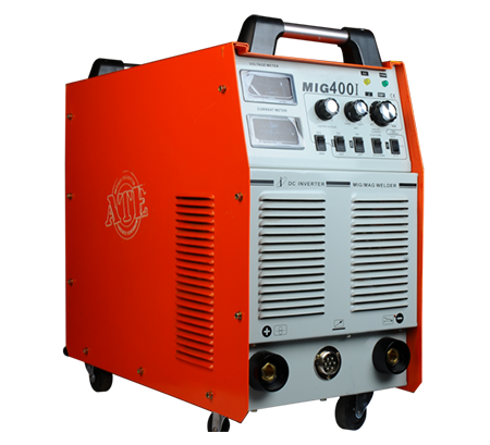 | MIG Welding Machine High-Speed and Versatile Welding Solutions At ATE Welding Engineering & Robotic Automation, we offer advanced MIG (Metal Inert Gas) welding machines... View product → |
Frequently asked questions
Which welding process fits each automotive production task?
Use resistance spot welding for overlapping sheet-metal joints, MIG welding for flexible fabrication, TIG for precise thin or visible welds, and laser welding when low distortion and high speed justify the investment.
Is a flux core welder a practical alternative to MIG for automotive work?
Flux core welding suits thicker steel, outdoor work and surfaces that are difficult to clean. MIG is usually the better choice for clean, thin automotive sheet metal because it produces less slag and supports faster cleanup.
How should you match the machine to automotive materials and operating conditions?
Match the power source, wire, shielding gas, torch, polarity and duty cycle to the material thickness, alloy, joint design, production rate and available ventilation.
When does a manual station become a robotic automotive welding cell?
Move to a robotic cell when repeatable high-volume joints, consistent cycle times and reduced operator variability outweigh the cost of programming, fixturing, guarding and maintenance.
What should you verify before approving an automotive welding system?
Verify sample weld quality, joint access, fixture repeatability, cycle time, wire feeding, safety guarding, controls integration, maintenance access and documented inspection results.
Related products
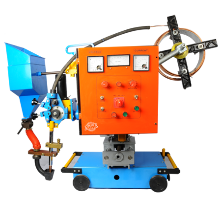 | ARC Welding Machine High-Efficiency Welding Solutions At ATE Welding Engineering & Robotic Automation, we provide advanced Submerged Arc Welding (SAW) machines designed... View product → |
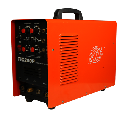 | TIG Welding Machine Precision and High-Quality Welding At ATE Welding Engineering & Robotic Automation, we specialize in TIG (Tungsten Inert Gas) welding machines,... View product → |
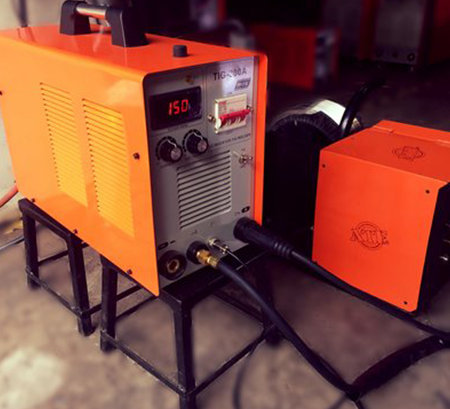 | The Cold Wire Feeder Welding Cold Wire Feeder Welding – Precision and Efficiency in Welding At ATE Welding Engineering & Robotic Automation, we offer Cold Wire Feeder Welding... View product → |