High-volume welding is not decided by peak amperage or the highest deposition-rate claim. Compare the wire process, duty cycle, cleaning time, feeding system, shielding conditions and takt-time requirements to determine which setup delivers more finished welds with less rework.
Key takeaways
- Choose solid-wire MIG for clean indoor work and controlled gas shielding.
- Choose flux core welding for outdoor work, drafts and thicker steel.
- Calculate cost per finished weld, including gas, wire, cleanup and downtime.
- Size the machine by duty cycle, wire diameter, amperage and production takt time.
Which process fits your steel, joint and workplace?
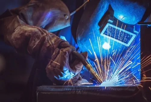
Choose a mig welder or flux core welder by matching the process to the steel, joint and workplace before comparing output. A conventional MIG setup uses solid wire and externally supplied shielding gas through the torch.
A flux core welder feeds tubular wire: FCAW-S generates its own shielding, while FCAW-G uses external gas, so not every tubular-wire process is gasless.
| Process | Best fit | Main trade-off |
|---|---|---|
| Solid-wire GMAW | Clean, thin-to-medium carbon steel indoors; repetitive joints and frequent starts | Low cleanup and good appearance, but drafts disrupt gas shielding |
| FCAW-G | Heavier carbon or low-alloy steel, larger welds and high deposition | More weld metal, but slag removal, gas control and interpass cleaning add time |
| FCAW-S | Outdoor work, wind exposure or sites where cylinders and regulators are impractical | No shielding gas, but more smoke, spatter and slag |
Use short-circuit GMAW for thin sheet and frequent starts and stops. Spray or pulsed-spray transfer can raise deposition and reduce spatter, but it requires compatible wire, gas, current range and enough base-metal thickness to prevent burn-through.
Check the selected wire’s positional rating before choosing a transfer mode or weld position; high-deposition settings may not suit vertical or overhead joints. FCAW procedures also set polarity, fit-up limits, preheat and interpass temperatures. Poor fit-up increases bridging and defects, while skipping temperature controls can cause cracking or hydrogen-related failures.
Which process produces the lowest cost per finished weld?
Solid-wire MIG often delivers the lowest cost per finished weld in repetitive indoor cells, while larger-diameter FCAW-G can win on heavy sections. Arc deposition rate is not production throughput: travel speed, arc-on time, rated duty cycle, cleaning, changeover and repairs determine the finished cost.
| Cost factor | Solid-wire MIG | FCAW-G or FCAW-S |
|---|---|---|
| Wire and gas | Lower wire price; requires cylinders or bulk gas | FCAW-G uses wire and gas; FCAW-S removes gas-management cost |
| Post-weld work | No slag between passes; less grinding and spatter cleanup | Slag removal, brushing, spatter cleanup and disposal add minutes |
| Cell overhead | Lower extraction and torch-cleaning demand | More smoke and spatter can increase extraction and cleaning |
| Heavy welds | May need more passes and arc-on time | Larger-diameter FCAW-G can deposit more metal per minute |
| Downtime | Measure spool changes, gas-cylinder changes, tips, nozzles and liners | Measure wire changes, contact-tip wear, slag removal and repairs |
A higher deposition rate loses its value if the operator or robot spends those minutes chipping slag, grinding, cleaning the nozzle or correcting porosity. FCAW-S avoids regulators and cylinders but can increase smoke, spatter and slag in a fixed cell.
For each batch, calculate:
- Consumable cost = wire mass × wire price, plus gas, tips, nozzles, liners, extraction and slag disposal.
- Production time = arc-on minutes plus cleaning minutes plus spool-change and gas-cylinder-change downtime.
- Finished cost = total batch cost plus rejected or repaired welds, divided by accepted weld length or weld count.
Run the same batch with a MIG welding machine and flux core welder, then compare those measured figures rather than deposition rate alone.
How should you size the machine for continuous production?
Peak amperage does not size a production cell. Match rated output amperage and duty cycle to wire size, weld size, plate thickness, joint design and production takt time, then compare a basic mig welding machine with an industrial mig welder under identical conditions.
- Treat duty cycle as the percentage of a ten-minute period that the power source can weld at a stated current and ambient condition. Compare the same test standard and ambient temperature; a 400-amp peak rating proves little if the machine cannot sustain the required current.
- Check wire-feed range, supported wire diameters, spool capacity, drive-roll type, liner length, feeder location, torch length, cooling method, power supply and service access.
- Specify feeding hardware for the job. Long conduit runs, soft aluminium wire and tubular FCAW wire need suitable drive-roll pressure, liner selection and tension.
- Ask how the machine controls burnbacks, bird-nests and unstable arc starts. Feeding faults can erase the output advantage of a larger mig welder.
- Calculate weld metal volume as weld cross-sectional area multiplied by weld length. Convert that volume to mass using steel density, divide by the stated deposition rate, and compare the resulting arc-on time with takt time.
- Add wire changes, cleaning and maintenance to the cycle. Select the higher-rated power source only when its duty cycle and feeder sustain that takt without overheating or intervention.
For example, 0.8 kg of weld metal at 4 kg per hour requires 12 arc minutes. A ten-minute takt cannot contain that work, even before changeover time; increase deposition, add parallel stations or redesign the cycle.
How do gas choice, drafts and maintenance affect weld quality?
A 100% carbon dioxide supply usually gives deeper penetration and may cost less per cylinder in some supply arrangements, but it produces a harsher arc and more spatter. Argon-rich blends run more smoothly with less spatter; select the blend for the wire classification, transfer mode and joint requirements.
| Gas | Operating effect | Production consequence |
|---|---|---|
| 100% carbon dioxide | Strong penetration, harsh arc, more spatter | Lower cylinder cost in some supply arrangements, but more cleanup and possible rework |
| Argon-carbon-dioxide blend | Smoother arc and lower spatter | Better appearance and less cleanup when matched to wire and transfer mode |
A mig welding machine or gas-shielded flux core welder needs a sound shielding circuit. Check the regulator, hose, fittings, solenoid, torch connections and flowmeter for leaks, then verify flow at the torch. Raising the setting will not cure porosity if a leak, draft or excessive flow is creating turbulence.
- Enclose the weld zone or control airflow around an industrial mig welder and FCAW-G cell; drafts disturb the shielding envelope.
- Set contact-tip-to-work distance and torch angle consistently, remove nozzle buildup, and replace a damaged liner.
- Use extraction and fume controls without directing airflow across the arc.
- Program interpass cleaning for a flux core welder; solid-wire GMAW generally needs simpler torch maintenance because it has no slag layer.
- Qualify the procedure for polarity, hydrogen controls, preheat and interpass temperature, and confirm slag removal between FCAW passes.
A practical decision rule for a high-volume welding cell
Choose solid-wire MIG for an indoor cell with clean steel, repetitive joints, thin-to-medium sections, important appearance and expensive post-weld labor. Choose a flux core welder when deposition rate justifies slag removal.
| Option | Select it when | Check before production |
|---|---|---|
| Solid-wire MIG | Clean indoor steel, repetitive joints and low cleanup | Wire diameter, gas, fit-up and transfer range |
| Gas-shielded FCAW | Heavy steel, large welds and high deposition outweigh slag removal | Wire classification, position rating and procedure limits |
| Self-shielded FCAW | Outdoor wind, mobility or impractical cylinders and regulators dominate | Smoke, spatter, slag and extraction capacity |
For gas-shielded FCAW, confirm polarity, diffusible-hydrogen controls, preheat and interpass limits in the welding procedure. An industrial MIG welder does not win on rated amperage alone; the process must survive the complete shift.
Run a production trial using the intended wire diameter, gas, joint fit-up, torch or robot path and shift length. Record:
- Finished weld length per hour
- Arc-on percentage
- Wire use and gas use
- Cleaning minutes
- Contact-tip and nozzle changes
- Defects and repairs
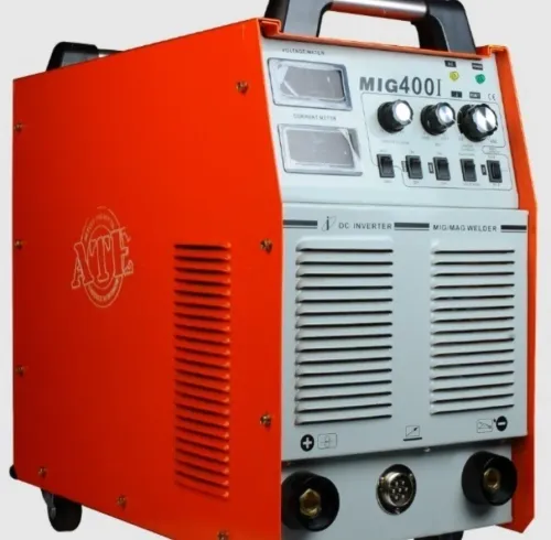
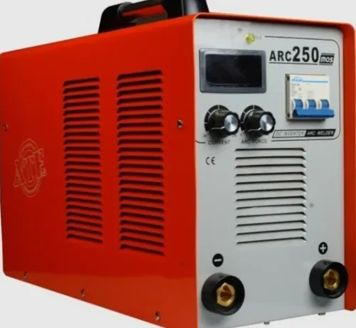
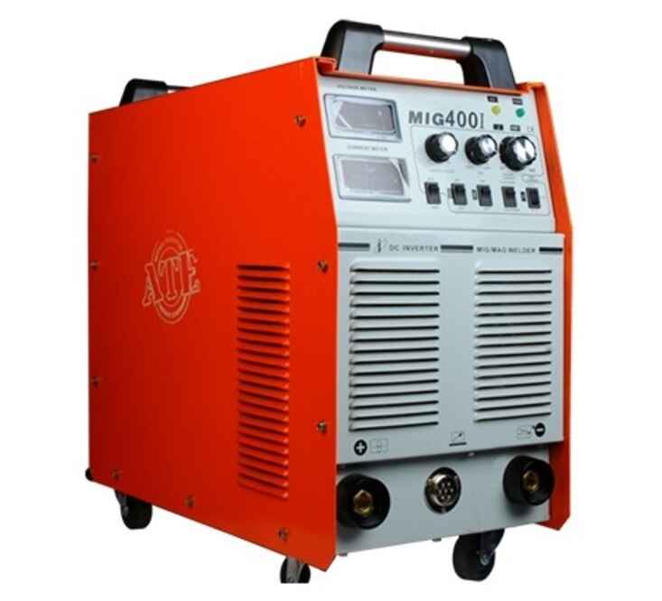
ATE WELDING ENGINEERING ROBOTICS AND AUTOMATION PRIVATE LIMITED can help a Pune manufacturer validate the power source, feeder, torch and automation arrangement against those measured conditions. Select the mig welder from the trial data, not its product label.
Related product
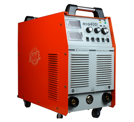 | MIG Welding Machine High-Speed and Versatile Welding Solutions At ATE Welding Engineering & Robotic Automation, we offer advanced MIG (Metal Inert Gas) welding machines... View product → |
Frequently asked questions
Which process fits your steel, joint and workplace?
Solid-wire MIG suits clean steel, controlled indoor joints and low-spatter production. Flux core welding suits outdoor work, drafts and thicker or less-clean steel when you can remove slag.
Which process produces the lowest cost per finished weld?
Compare wire cost, shielding gas, deposition rate, spatter, slag removal, rework and downtime. Solid-wire MIG often reduces cleanup, while flux core can avoid gas costs and tolerate harsher workplaces.
How should you size a MIG or flux core welding machine for continuous production?
Match amperage, wire diameter and duty cycle to the weld schedule, then allow capacity for peak loads, pauses, heat buildup and the required production takt time.
How do gas choice, drafts and maintenance affect weld quality?
Use the gas specified for the wire and steel, protect the shielding zone from drafts, and maintain the liner, contact tip, nozzle, drive rolls, ground clamp and gas path.