A flux-cored setup feeds a tubular electrode continuously while an arc melts both the wire and the workpiece, creating a weld pool beneath shielding products and slag. By following the wire, polarity, gas, travel, and cleaning requirements, you can identify what is happening at each stage and set up the process without confusing FCAW with ordinary solid-wire MIG.
Key takeaways
- Use electrode-negative polarity for self-shielded flux-cored wire.
- Match wire diameter, material, shielding gas, polarity, voltage, and wire speed.
- Remove slag between passes and inspect for porosity, undercut, and lack of fusion.
- Choose flux-cored welding for outdoor work, thick steel, or high-deposition production.
What the Arc and Flux Are Doing Inside the Joint
A constant-voltage power source feeds a continuous tubular electrode, and the arc melts both wire and base metal into the joint. That is the MIG welder working process in electrical terms, but a flux-filled wire makes the operation flux-cored arc welding, not solid-wire GMAW.
1. The feeder pushes the tubular wire through the liner, gun, and contact tip toward the workpiece. The wire completes the circuit when it touches the grounded metal.
2. The power source establishes an arc and maintains its voltage as the wire melts. Arc heat liquefies the electrode and part of the base metal, forming a weld pool.
3. Flux inside the electrode decomposes in the arc. Its products shield the pool, while molten flux forms slag over the bead as it solidifies.
FCAW-S, or self-shielded flux-cored arc welding, normally uses no gas cylinder: the flux supplies the shielding products. FCAW-G, or gas-shielded flux-cored arc welding, uses flux plus carbon dioxide or an argon/CO2 mixture delivered through the gun.
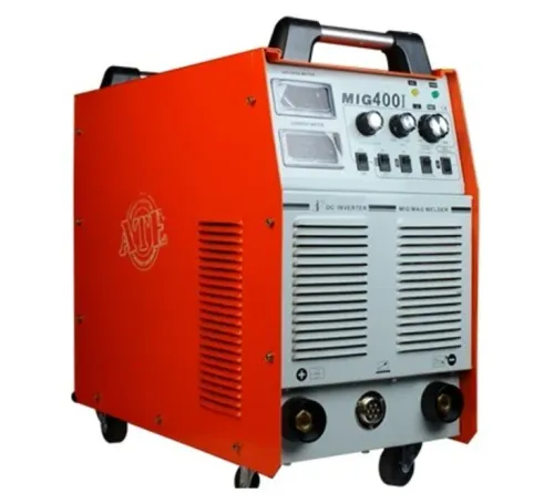
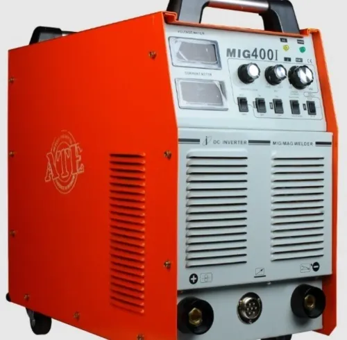
The phrase “mig welding machine for flux core welder process” means a CV MIG power source configured for flux-cored work. The feeder, liner, drive rolls, gun, contact tip, and polarity must match the wire.
Calling the machine a MIG welder does not change the process classification: flux-cored wire means FCAW, even when the same machine also runs solid-wire GMAW.
How to Set Up and Start a Flux-Cored Weld
1. Identify the wire classification on the spool and data sheet, then confirm whether it is FCAW-S or FCAW-G. FCAW-S normally needs no shielding cylinder; FCAW-G requires the specified external gas.
2. Fit the correct spool. Install drive rolls with the groove matched to the wire diameter, inspect the liner for blockage or damage, and set spool-brake tension so the reel stops without overrunning. Fit a contact tip sized for the wire.
3. Thread the wire through the liner and confirm smooth feeding without bird-nesting or excessive drag. Connect the work lead to a clean grounding clamp and secure it to bright metal.
4. Connect the regulator, hose, and gas cylinder only when the wire data sheet calls for external shielding. Select the required polarity at the machine terminals before welding; do not assume FCAW-S and FCAW-G use the same setting.
5. Make the joint fit-up, then remove mill scale, oil, paint, moisture, and heavy rust from the weld area. Use the manufacturer’s settings chart for wire diameter, material thickness, position, voltage, wire-feed speed, gas, and stickout.
6. Hold the gun at the specified contact-tip-to-work distance, use a slight drag angle so the slag trails behind the pool, press the trigger, and move at a steady speed. This sequence is the core of flux core welder operation; an excessive stickout or rushed travel speed can produce poor fusion and porosity.
How to Match Wire, Polarity, and Machine Settings
Choose the wire before choosing the amperage: diameter and AWS classification must match steel thickness, joint type, welding position, and required impact or usability characteristics. E71T-1, E71T-11, and E71T-8 are not interchangeable because they fit the same feeder; their shielding requirements, position capability, and performance differ.
1. Confirm polarity from the wire manufacturer’s data sheet. Many self-shielded wires use DCEN, while many gas-shielded flux-cored wires use DCEP. The wrong polarity can produce spatter, unstable arc behavior, poor penetration, or an unacceptable bead profile.
2. On a constant-voltage system, set wire-feed speed first because it primarily controls amperage and deposition. Increasing wire-feed speed generally raises current. Set voltage next: it mainly changes arc length and bead shape. Too little voltage creates a harsh, stubbing arc; too much creates a long unstable arc, spatter, or undercut.
3. Set travel speed and stickout from the published chart. Excessive stickout preheats the wire, reduces effective arc energy, and can cause insufficient fusion. Too little stickout overheats the contact tip and encourages burnback.
4. Adjust one variable at a time, staying within the manufacturer’s chart range for that wire, diameter, position, gas, and thickness. Watch the arc and bead rather than chasing a nominal amperage; repeatable settings matter in any MIG welding machine process, including mechanized work.
A flux core welder also needs consistent torch angle, fit-up, and joint gap.
What Happens to the Weld Pool, Slag, and Defects
Once the arc starts, it melts the tubular wire and part of the base metal into a weld pool. The flux decomposes into shielding gases and forms molten slag over the bead as it solidifies. The bead is not ready for another pass until the slag is removed.
- Keep a slight drag angle so the arc stays ahead of the slag and the slag trails behind the pool. Pushing can drive slag into the leading edge and increase inclusion risk.
- Chip or mechanically remove the slag after the pass, then brush the weld clean.
- Inspect the bead, crater, and tight corners for slag islands, cracks, or unfused areas.
- Clean the joint before the next pass. Welding over an incompletely cleaned crater can trap nonmetallic inclusions beneath the new layer.
Porosity or worm tracking can point to mill scale, oil, paint, moisture, heavy rust, damp wire, poor gas coverage, a draft, blocked nozzle, excessive torch distance, high travel speed, or an unsuitable voltage-and-stickout combination. Trapped gas can escape through a rapidly freezing bead and leave surface channels.
Gas-shielded FCAW requires draft protection, an intact hose, an unobstructed nozzle, and correct regulator flow. Self-shielded FCAW needs no cylinder, but wind can disperse its shielding products. Smoke, spatter, and slag remain significant, so use local fume extraction and the required respiratory controls even without an external gas supply.
When This Process Fits a Production or Site Welding Job
Flux-cored welding fits production and site work when you need a continuous electrode, higher deposition potential than manual stick welding, and tolerance for heavier steel fabrication. It produces more smoke, spatter, and slag than solid-wire GMAW, so it is a poor choice where cleanup or indoor fume control is limited.
| Option | Strength | Main cost or risk |
|---|---|---|
| Flux-cored welding | Continuous wire and high deposition potential | Smoke, spatter, slag, and stricter cleaning |
| Manual stick welding | Portable and simple equipment | Electrode changes interrupt output |
| Solid-wire GMAW | Clean bead and little slag | Gas shielding is vulnerable to drafts |
Flux core welding in Pune is not selected because of the city. Joint design, steel grade, wire classification, thickness, welding position, ventilation, dust, humidity, and drafts determine the process.
For shop, outdoor, or monsoon work, store wire in a dry enclosure, clean mill scale, oil, paint, rust, and moisture from the joint, protect gas lines from damage and drafts, and use fume extraction. FCAW-S still produces hazardous fumes; no cylinder does not make poor ventilation safe.
Mechanized or robotic welding stays repeatable only when these variables remain controlled:
- Torch angle, stickout, travel speed, wire-feed speed, fit-up, joint gap, and torch alignment
- Liner drag, contact-tip wear, and wire bird-nesting
- Wire classification, polarity, and settings data
A manufacturer or fabricator evaluating the process with ATE WELDING ENGINEERING ROBOTICS AND AUTOMATION PRIVATE LIMITED should request the complete configuration: power source, feeder, torch, consumables, polarity, settings data, and automation interface—not just an amperage rating.
Related product
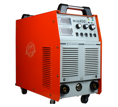 | MIG Welding Machine High-Speed and Versatile Welding Solutions At ATE Welding Engineering & Robotic Automation, we offer advanced MIG (Metal Inert Gas) welding machines... View product → |
Frequently asked questions
What is happening inside the joint during flux-cored MIG welding?
A constant-voltage machine feeds tubular wire through the gun. The arc melts the wire and base metal, while the flux creates shielding gases and a slag layer over the cooling weld pool.
How do you start a weld with a flux core welder?
Install the correct drive rolls and contact tip, thread the wire, connect the work clamp, set polarity, adjust voltage and wire-feed speed, and clean the joint before striking the arc.
How do you match wire, polarity, and machine settings?
Read the wire manufacturer’s label first. Self-shielded wires commonly use electrode-negative polarity, while gas-shielded wires commonly use electrode-positive polarity; set voltage and wire speed within the listed range.
What defects can occur in flux-cored welding?
Porosity, slag inclusions, undercut, lack of fusion, excessive spatter, and burn-through result from contamination, incorrect travel angle, poor settings, trapped slag, or excessive heat.
When does flux-cored welding suit production or site work?
It fits thick-steel fabrication, outdoor welding with self-shielded wire, and production work that needs high deposition. Use solid-wire GMAW when cleaner welds, lower cleanup, and controlled indoor conditions matter more.