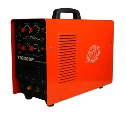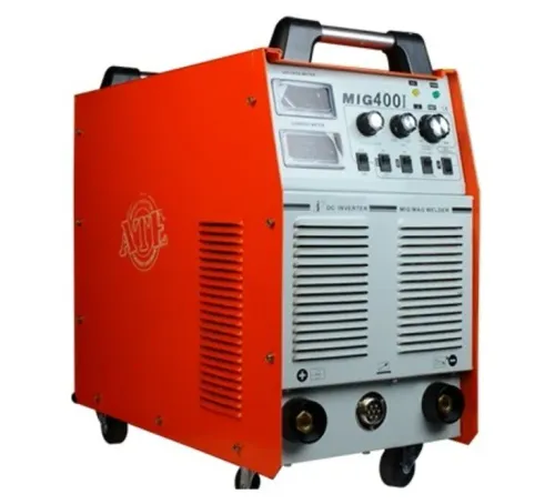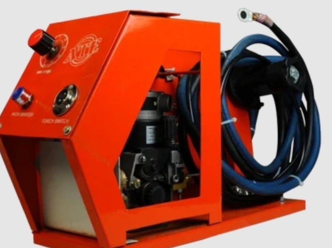
A flux-cored wire feeder does more than push filler metal: it delivers the continuously fed electrode, transfers welding current through the contact tip, and coordinates the arc with the power source. By following the wire path and control sequence, you can identify the parts that govern feed consistency, set them correctly, and separate mechanical faults from incorrect electrical settings.
Key takeaways
- Set spool tension to stop overrunning without adding drag.
- Match drive-roll type and pressure to tubular wire diameter.
- Confirm polarity, shielding gas, liner, and contact-tip size before welding.
- Check liner friction, tip blockage, and roll slip during feed failures.
How the Wire Travels from the Spool to the Arc
A flux core welder moves tubular electrode wire through a continuous path: spool or drum, adjustable spool brake, inlet guide, drive-roll assembly, gun liner or conduit, contact tip, and arc. The brake prevents the spool from overrunning while the drive rolls push the wire forward.
Flux-cored wire supplies both filler metal and the consumable electrode. In cold wire feeder welding, a separate filler wire enters an existing arc, laser, plasma stream, or other heat source and is normally not electrically energized. In FCAW, welding current travels through the contact tip and wire.
At the arc, the wire and workpiece melt together; the flux core generates shielding species and leaves protective slag.
Every transition must align with the next:
- Center the inlet guide with the drive-roll groove. An offset guide adds drag and can cause slipping or surging.
- Match liner length and seating to the gun. A liner that is too long, too short, dirty, or kinked changes resistance.
- Keep the conduit bend radius generous. A sharp bend can make push feeding unstable.
- Seat the contact tip correctly and match its bore to the wire diameter. Poor alignment disrupts arc length.
The feeder display shows commanded welding wire feeding speed, not guaranteed speed at the arc. High friction or any misalignment can reduce actual wire movement, producing an intermittent arc even when the displayed setting remains unchanged.
How Drive Rolls Grip Tubular Flux-Cored Wire
The drive roll must match both the wire construction and its actual diameter. Knurled or serrated rolls usually provide the traction needed by tubular flux-cored wire without excessive pressure; V-groove rolls suit wire constructions that could be damaged by aggressive teeth. Check the feeder manual and the wire manufacturer’s recommendation rather than choosing by appearance.
- Read the diameter stamped on the spool, then install rolls with that exact groove size. A mismatched groove slips or crushes the tube.
- Install each roll in the specified orientation. Follow the feeder diagram and place any marked, keyed, or profiled face where the manufacturer shows it.
- Thread the wire through the correctly sized inlet and outlet guides, keeping the path aligned with the liner. An offset guide adds drag before welding begins.
- Back off roll tension, then perform the feeder manufacturer’s safe slip test. Use a nonconductive surface or the specified test method, and increase pressure only until the rolls feed reliably without slipping.
Too little pressure causes slipping, surging, and inconsistent welding wire feeding. Too much pressure flattens tubular wire, crushes its flux core, sheds debris into the liner, and increases resistance; the flux core welder then works harder without gaining dependable grip.
If bird-nesting forms at the liner entrance, do not simply tighten the rolls. Cut out the damaged wire and inspect downstream resistance, guide alignment, roll installation, liner condition, spool-brake tension, and conduit routing, including tight bends. A push-only system becomes less forgiving as length, bends, and friction increase.
How Shielding, Polarity, and Contact-Tip Geometry Change the Feed Setup
Choose the wire classification before connecting a flux core welder. FCAW-G sends shielding gas through the gas hose and gun nozzle; FCAW-S creates shielding from its flux and uses no external gas.
The flux core welding process still depends on clean, dry wire: moisture, oil, rust, or damaged flux can cause spatter, porosity, and irregular feeding.
1. Read the wire classification and manufacturer data for polarity. Many FCAW wires use DCEP, while some self-shielded FCAW-S classifications require DCEN. Do not select polarity from the words “flux core” alone.
2. For FCAW-G, set the specified gas flow, clear spatter from the nozzle, and shield the arc from drafts. A feeder can deliver wire correctly while poor gas coverage leaves porosity in the weld.
3. Fit a contact tip whose bore matches the actual wire diameter and construction. The tip transfers welding current as well as guiding the electrode; a worn or oversized bore lets the wire wander, causing arc-length variation, spatter, and poor starts.
4. Set tip stick-out and CTWD from the qualified welding procedure. Increasing electrode extension preheats more wire, raises melting rate at the same wire-feed speed, and generally lowers current in a constant-voltage system. Shortening it changes the bead and penetration.
Do not choose CTWD or nozzle-to-tip position by appearance. The qualified procedure controls those dimensions, because changing them changes electrical resistance, deposition, arc stability, and penetration.
What Happens After You Press the Trigger
Pressing the trigger starts a timed sequence, not just the feeder motor. In the flux core welding process, the control coordinates welding wire feeding, gas, arc initiation, and wire-stop timing so the electrode reaches the work without a harsh start.
1. The feeder motor starts at the programmed run-in speed, then accelerates toward the commanded wire-feed speed. Run-in reduces the chance that cold, fast-moving wire will stub into the work; excessive run-in delays arc transfer or produces an unstable start.
2. On FCAW-G equipment, gas preflow runs for its programmed time before arc initiation. The power source then establishes the arc as the flux-cored wire contacts the workpiece.
3. With a constant-voltage source, increasing wire-feed speed raises the wire melting rate and usually increases current, penetration, and deposition. Set wire-feed speed and arc voltage together for the wire diameter, polarity, steel grade, CTWD, and welding position; there is no universal setting.
4. Releasing the trigger stops the feeder and begins the programmed ending sequence. Burnback melts the remaining wire clear of the contact tip without creating an excessive stub.
Burnback is not crater fill, downslope, postflow, or wire retract. Too little burnback lets the wire freeze into the tip; too much melts the wire back into the tip or leaves a difficult restart. CTWD also changes the result: longer extension preheats more wire, increases melting rate at a given speed, and generally lowers current.
That is how flux core welder feeding works from trigger press to wire stop.
How to Diagnose Feed Failures and Specify a Complete System
When an arc turns erratic or the wire burns back into the contact tip, inspect the complete feed path before replacing parts. Check feed torque, drive-roll slip, CTWD, tip wear, liner contamination or kinks, wire-stop timing, and arc-start parameters.
- Reduce roll pressure and perform the feeder manufacturer’s controlled slip test.
- Confirm the inlet guide, roll groove, liner, conduit, and contact tip match the wire diameter.
- Check that the spool brake is not creating excessive drag.
- Measure CTWD against the qualified welding procedure.
- Adjust run-in and burnback timing after correcting mechanical resistance.
For a bird-nest, cut out all damaged wire before rethreading. Inspect the inlet guide, roll pressure, liner, spool brake, conduit bend radius, and guide alignment; tightening the rolls alone can force more wire into the blockage.
Keep flux-cored wire away from moisture, oil, and rust. Contamination causes irregular welding wire feeding, spatter, and porosity even when the machine is mechanically sound.
Feeding choice changes as resistance rises:
| Option | What it means | When it applies |
|---|---|---|
| Push-only | Feeder motor pushes wire through the conduit | Short, well-routed torch leads |
| Push-pull | Feeder and torch motors share the feed load | Longer conduits, more bends, or softer wire |
| Motorized torch | Torch-mounted motor drives wire near the arc | Robotic or long-reach layouts |
For robotic work, specify conduit length, bends, torch routing, wire straightening, tip-to-work geometry, and robot TCP repeatability. ATE WELDING ENGINEERING ROBOTICS AND AUTOMATION PRIVATE LIMITED can help match the feeder, torch, power source, and automation layout as one flux core welder system rather than selecting a motor by rating alone.
Related product
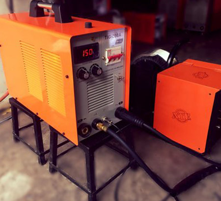 | The Cold Wire Feeder Welding Cold Wire Feeder Welding – Precision and Efficiency in Welding At ATE Welding Engineering & Robotic Automation, we offer Cold Wire Feeder Welding... View product → |
Frequently asked questions
How does wire travel through a flux core welder?
Wire travels from the spool through the brake, inlet guide, drive rolls, gun liner or conduit, contact tip, and arc.
How should drive rolls grip tubular flux-cored wire?
Use drive rolls made for flux-cored wire and apply enough pressure to feed consistently without crushing the tubular electrode.
How do shielding gas and polarity affect flux-cored wire feeding?
Gas-shielded and self-shielded wires use different setups, while wire specifications determine polarity and influence contact-tip and liner choices.
What causes flux core welder feed failures?
Inspect spool tension, inlet alignment, drive-roll pressure, liner friction, contact-tip blockage, wire diameter, and electrical connections.